Geomorphology

Model of Erosion and Tectonic Uplift

This is a basic implementation of a geomorphology model, combining erosion due to rainfall and toppling with tectonic uplift. It is implemented as a stochastic cellular automaton grid, where the state of each cell consists of the topological height h, the drainage area to a cell, and the watercolumn w. In the beginning, the heights of the cells represent a (discretized) inclined plane. Rainfall is encapsulated in the drainage network representing a river system. Drainage is always passed from one cell to its lowest grid neighbor; sinks are filled with water (watercolumn) and the overflow receives the drainage upstream from the lake. The higher the drainage area to a cell, the more water flows over this cell. Stream power erodes sediments over time. Additionally, a stochastic process of toppling is considered.
model image
model image
The relief map of the system in a steady state balancing tectonic uplift and stream power erosion.
model image
model image
The drainage network representing the river system in a steady state balancing tectonic uplift and stream power erosion.
Model state snapshots: the relief map (left) and drainage network representing the river system (right) in a steady state balancing tectonic uplift and stream power erosion. (click to enlarge)

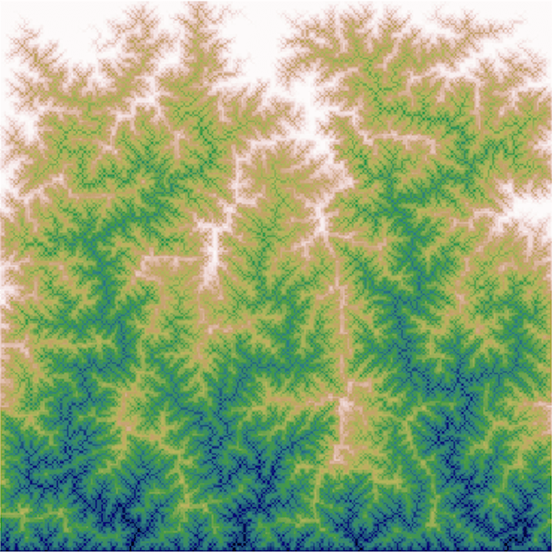
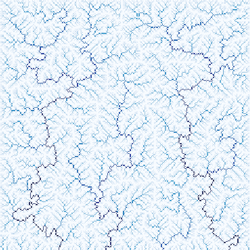
In order to observe the formation of a river network, the cell heights are initialized as an inclined plane. The drainage network is a fictional construct, integrating continuous rainfall over time. It translates to the size and stream power of a river at the cell.

Algorithm

The erosion process is implemented by asynchronously updating all the cells (in one time t) according to the following steps:

  1. Uplift:

    The height of each cell is incremented, representing uplift.

  2. Set drainage network:

    1. Map all cells to their lowest neighbor; if none is lower than the cell itself, the cell is mapped to itself.

    2. Fill sinks (no lower neighbor) with water, such that a lake forms and one of the lake cells has a lower neighbor or is an outflow boundary. All lake cells point to this cell.

    3. Set drainage area. For every cell, pass the cells assigned drainage area (default 1., cummulated with that receved from other already called cells) downstream through the already initialized network (adding the drainage area to every cell on the way) and dump it on any cell passed by, that was not yet called or is an outflow boundary.

  3. Stream power erosion

  4. Toppling:

    With a frequency f per cell evaluate the failure probability for slope. If toppling occurs, the slope is reduced to 1/3 of its initial value.